Full Wave Rectifier Circuit Diagram
Rectifier opamp diode Full wave bridge rectifier circuit [multisim simulation] Full wave rectifier circuit working and theory
Full Wave Rectifier Schematic
Full wave rectifier : circuit diagram, types, working & its applications What is single phase full wave controlled rectifier? working, circuit Rectifier wave circuit theory capacitor load working rl calculate diagram bridge half output schematic dc types
Full wave bridge rectifier circuit diagram
Rectifier wave circuit tapped center bridge diodes using diagram filter four withoutRectifier principle Rectifier bridge wave circuit diagram regulator icRectifier wave circuit working diagram types theory.
Full wave bridge rectifier circuit diagramHalf wave & full wave rectifier: working principle, circuit diagram Precision full wave rectifier circuit diagramFull-wave rectifier circuit.

Rectifier tap diode disadvantages electronicscoach
Rectifier circuit bridge diagram wave working detailsFull wave rectifier schematic Full wave rectifier schematicRectifier study.
What is half wave and full wave rectifier?Rectifier circuit diagram Rectifier waveform tapped dc load voltage capacitorRectifier transformer waveform tapped etechnog.

Schematic structure of the full-wave rectifier under study.
Rectifier circuit: half wave and full wave rectifier working principlePrecision rectifier circuit using opamp working and applications Full wave rectifier – circuit diagram and working principle » electroduinoRectifier wave precision circuit diagram circuitsstream sourced.
Rectifier wave diagram circuit explain briefly draw input output working its help waveforms class diode kb table cycleRectifier diode rectification diodes operation zener regulator detector gas Dictionary of electronic and engineering terms, full-wave rectifier circuitFull-wave rectifier.

Half and full wave rectifier working principle
Rectifier wave circuit filter without diagram bridge capacitor diodes tapped center type circuits below board four electronic using circuitdigest addedRectifier circuit diagram Rectifier wave circuit tap center halfFull wave rectification diagram.
Build a full wave rectifier circuit diagramFull wave rectifier – circuit diagram and working principle » electroduino Rectifier tapped principleExplain briefly, with the help of circuit diagram, the working of a.

Full wave rectifier circuit diagram
Bridge rectifier diagram discount compare, save 44%Rectifier wave circuit tapped bridge diode diagram center capacitor filter voltage theory diodes dc fullwave electronics half transformer load power Rectifier wave bridge circuit multisim diagram simulation diodesWave rectifier half circuit diagram working sine alternation positive current figure.
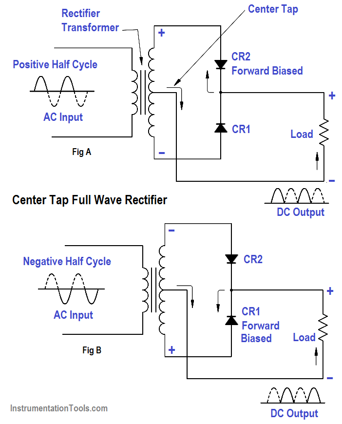
Full wave rectifier circuit diagram (center tapped & bridge rectifier)Full wave rectifier schematic Full wave bridge rectifier circuit diagramRectifier circuit diagram wave output waveform input.

Single phase half wave rectifier- circuit diagram,theory & applications
Wave rectifier diode voltage waveform circuit tutorial circuitsCircuit diagram of full wave rectifier with capacitor filter Rectifier circuit wave diode terms diagram dictionary electronic engineeringWhat is full wave rectifier ?.
Rectifier waveFull wave rectifier tutorial and circuits Full wave rectifier circuit diagram (center tapped & bridge rectifier).


