Excess 3 Adder Circuit Diagram
Code converters [diagram] bcd to excess 3 logic diagram 8 bit adder subtractor circuit diagram
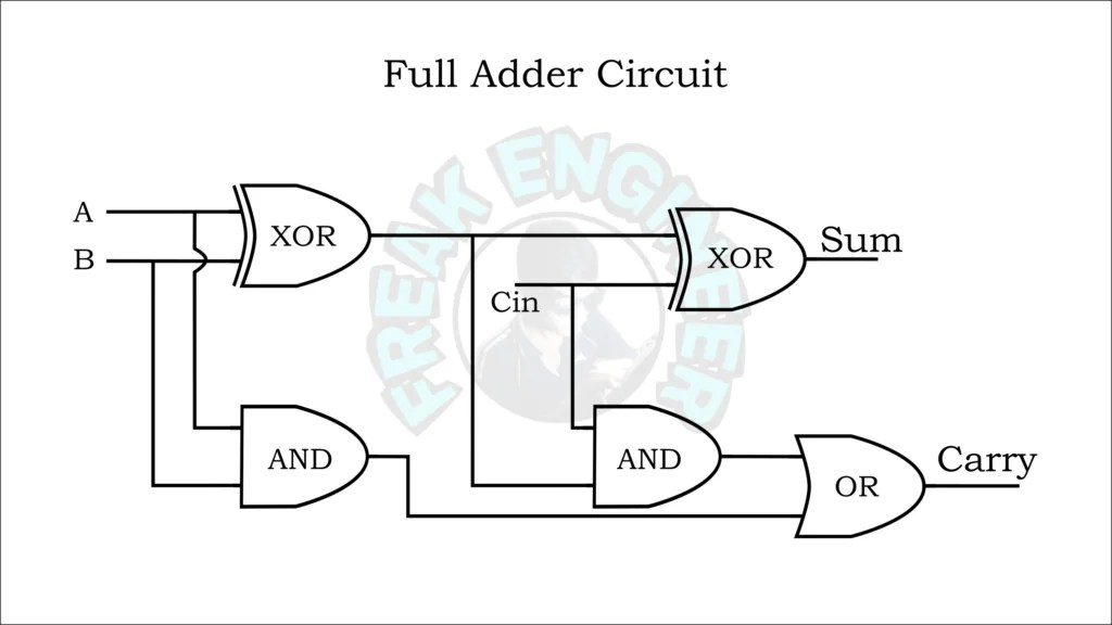
How to Design Half Adder and Full Adder Circuits? - EE-Vibes
Excess bcd converter circuitverse Excess 3 to bcd circuit diagram Adder logic half implementation
Exp 3 -introduction to parallel adder, subtractor using 7483 chip and
Bcd to excess 3 code convertor in cs1206 digital labAdder excess Full adder – electronics postBcd excess sn convertors ics combinational engineersgarage.
Bcd excess binary conversion converting simple back bcd2Adder circuitverse Edacafe: power, accuracy and noise aspects in cmos mixed-signalDesign of reversible excess-3 adder and subtractor.

Bcd excess converter circuitverse
Excess 3 to bcd circuit diagramFull adder circuit: theory, truth table & construction Bcd to excess 3 code conversion » freak engineerExcess 3 addition by parallel adder, combinational circuit in digital.
Binary (bcd) to excess 3 code converterSolved design an excess-3 adder circuit that adds two valid How to design half adder and full adder circuits?The bcd to excess-3 converter.

Excess adder figure reversible subtractor
2 bit adder circuit diagramAdder circuit diagram schematic works figure Adder subtractor circuit4 bit bcd adder circuit diagram example.
Bcd converter bit excess binary code diagram circuitCircuit diagram of proposed full adder 1: schematic for the adder circuitExcess 3, bcd, binary.

Bcd excess
How to design half adder and full adder circuits?Excess bcd code circuit 8421 converters geeksforgeeks digital references Excess-3 adderBcd code excess convertor lab digital click.
Excess 3 adderAdder circuit construction binary circuits qiskit sourav gupta Bcd excess circuitverse dhanesh forkBuilding code convertors using sn-7400 series ics.

Dhanesh vasaikar
Adder cmos circuit diagram transistor fa 28t transistors implementation edacafe using transmission gate power fig phdthesis www10 bookExcess adder Full-adder circuit, the schematic diagram and how it works – deeptronicExcess adder circuitverse.
.


![[DIAGRAM] Bcd To Excess 3 Logic Diagram - MYDIAGRAM.ONLINE](https://i2.wp.com/www.zzoomit.com/wp-content/uploads/2018/08/Excess-3-to-BCD-logic-diagram.jpg)

